Modern Sliding Gate Designs for Homes Supplier in China | Aluminum Sliding Gate, Automatic Driveway Gate Specs and FOB Pricing
2. Aluminum Sliding Gate Profiles
3. Six Residential Configurations
4. Automatic Gate Motor Sizing
5. Cantilever vs Tracked
6. Safety Compliance
7. Wind Load and Deflection
8. Production and Coating
9. FOB Pricing and Payment
10. Foundation and Installation
11. Project Case: 42 Villas
12. Sliding vs Swing Gates
13. RFQ Checklist
14. Glossary
15. Related Products
What Defines a Modern Sliding Gate for Homes: Core Specification Sheet
A residential sliding gate is specified by four numbers: clear opening width, leaf height, solidity ratio, and duty cycle. Everything else – rail section, roller class, operator rating, foundation size – follows from those four. Modern sliding gate designs for homes span 3,000 to 6,000 mm of opening; outside that range the leaf stops behaving like a residential product and starts behaving like an industrial barrier, with a different operator class and a different foundation. The table below is the reference set used for export orders; deviations are engineered, not guessed.
Standard Dimensions and Clear Opening
Residential driveways are sized from the vehicle, not the plot boundary. A single-car opening needs 3,000-3,600 mm of clear width; a two-car or turning apron needs 4,500-6,000 mm. The leaf is always longer than the clear opening, because it must overlap the closing post and, on a tracked unit, cover the roller carriage at full retraction.
Leaf height above 2,400 mm pushes the centre of gravity far enough above the roller line that wind moment governs the carriage design. Above that height, split the leaf into a solid lower panel and an open upper section rather than increasing wall thickness.
Solidity Ratio and Privacy Rating
Solidity ratio φ is projected solid area divided by envelope area. It drives three things at once: wind drag, leaf mass, and how much of the driveway is visible from the street. Designers usually want high privacy; engineers want low φ. The compromise is a gradient – solid at eye level, open above 1,600 mm.
Finish Systems and Colour
Two finish routes are used for exterior gates. Polyester powder coating to Qualicoat Class 1 (minimum average film 60 µm) is the default; Class 2 (100 µm) is specified for coastal sites within 1 km of salt water. Anodizing to Qualanod AA15 or AA20 (15 or 20 µm oxide) is used where a metallic finish is wanted and the colour palette is limited to bronze, champagne, black and natural silver.
Aluminum Sliding Gate: Profile Sections, Alloy Temper and Wall Thickness
An aluminium sliding gate leaf is a welded or mechanically jointed frame: a top rail, a bottom rail that carries the rollers or the rack, two end posts, and intermediate verticals that hold the infill. The frame alloy, temper and wall thickness determine how far the leaf can span between supports without permanent set.
EN 755-2 Alloy and Temper Data
Extrusions are supplied to EN 755-2; the minimum mechanical properties below are the values used for section checks. 6063-T6 is the default for gate frame because it anodizes and powder coats cleanly and is readily weldable with 4043 filler. 6082-T6 and 6061-T6 are reserved for the bottom rail of cantilever leaves, where the bending moment is highest.
Design resistance for section checks uses EN 1999-1-1 partial factor γM1 = 1.10, giving an allowable bending stress of 155 MPa for 6063-T6 and 236 MPa for 6082-T6. Serviceability – not strength – governs almost every residential gate: a 4 m leaf in 6063-T6 at typical wind pressure reaches only 35-62 MPa of bending stress, roughly a quarter of the allowable, while the same leaf can sit close to the L/200 deflection limit.
Wall Thickness and Maximum Clear Span
Frame wall thickness is specified in three steps. The table gives the resulting second moment of area and section modulus for the four rectangular hollow sections stocked for gate frames, plus the deflection of the top rail spanning between end posts at a reference peak velocity pressure of 296 Pa (basic wind velocity 28 m/s, terrain category II, height 3 m – see the wind section for the derivation).
Deflection of the top rail at 296 Pa, tributary height 900 mm (a 1,800 mm leaf, rail carrying the upper half), simply supported between end posts:
Bottom Rail, Track and Roller Load Path
On a tracked leaf the bottom rail carries the entire vertical load through two or three roller assemblies to a ground rail; on a cantilever leaf the bottom rail is a continuous beam supported by a roller carriage housed in a concrete pit on the fixed side, with the free end cantilevered. The load path differs enough that the two types cannot share a rail section.
- Tracked: bottom rail 100 x 50 x 2.0 minimum; load spreads over 2 rollers at roughly 45-50% of leaf mass each, plus impact factor 1.25 when the leaf crosses a rail joint.
- Cantilever: bottom rail 150 x 75 x 3.0 in 6082-T6 for openings over 4,500 mm; the carriage resolves a moment equal to leaf mass × half the opening, so the rear roller pair carries roughly 65-70% of the total reaction while the front pair can go into uplift under wind suction.
- Roller bearings: sealed 6202-2RS or 6204-2RS deep-groove ball bearings, dynamic load rating C = 7.8 kN and 12.7 kN respectively. Bearing life at 30 cycles/day over 25 years is 273,750 cycles, which is well inside the L10 rating for either size at residential loads.
- Ground rail: 12 kg/m or 15 kg/m steel rail hot-dip galvanized to ISO 1461 (85 µm), cast into the driveway slab with M12 anchor plates at 500 mm centres.
Sand and grit are the dominant roller failure mode in Middle East and Australian installations. A sealed bearing with a double lip seal (2RS) and a rail scraper fitted ahead of the front roller extends service intervals from roughly 12 months to 36 months in those environments.
Aluminium Sliding Gate Design: Six Residential Configurations
The six configurations below cover the residential export range. Each is defined by infill geometry, which sets solidity, mass and the wind drag the operator has to overcome. Prices are FOB adders on the base tracked leaf.
Horizontal Slat, Semi-Privacy
The default modern design: 140 x 30 x 1.4 mm flat-oval slats at 160 mm pitch, giving a 20 mm sight gap and φ ≈ 0.62. Privacy is adequate at 20 m viewing distance; the gap keeps wind drag and leaf mass low enough for a 600 kgf operator up to a 5,000 mm opening. Slats can run full horizontal or be interrupted by a vertical feature post.
Full-Privacy Solid Panel
1.5 mm or 2.0 mm aluminium sheet, either flat or with a pressed cassette profile, welded into the frame. φ = 1.0. This is the heaviest and highest-drag option: a 6 m x 2 m leaf reaches 234 kg and 5,435 N of wind force at 296 Pa, which rules out light-duty operators outright. Use when the plot boundary faces a public street and local planning requires screen height above 1,800 mm.
- Sheet thickness 1.5 mm up to 2,000 mm leaf height, 2.0 mm above that.
- Pressed cassette or 40 mm box stiffener every 1,200 mm to stop oil-canning (visible panel ripple).
- Vent slots at 6-8% of panel area reduce net wind force by roughly 5-7% with no privacy loss.
Vertical Palisade
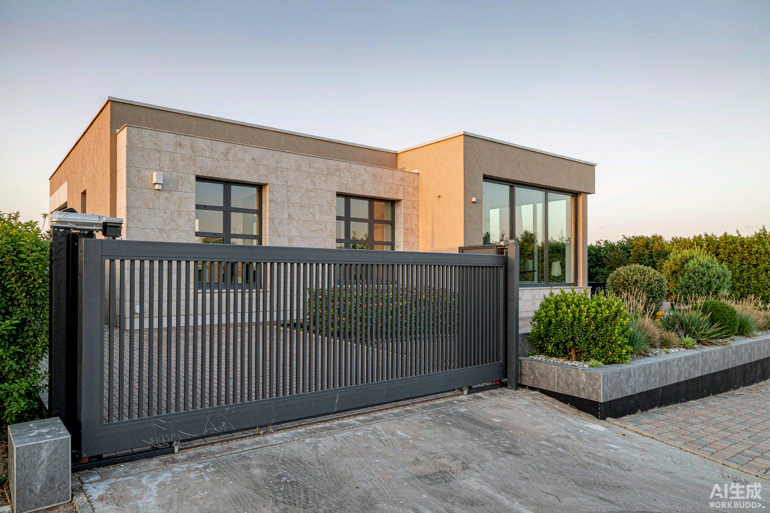
25 x 25 mm or 40 x 40 mm vertical bars at 120-140 mm centres, φ ≈ 0.33. The cheapest infill and the lowest wind load. Used where the gate is a boundary marker rather than a screen, or where a hedge behind the gate provides the privacy. Security value is high because vertical bars resist climbing better than wide slats, which act as a ladder.
Slat Plus Perforated Mesh Hybrid
A slat face backed by 1.5 mm perforated aluminium mesh (3 mm holes on 5 mm staggered pitch, 40% open area). φ rises to about 0.73 but sight lines are cut to near zero while airflow is only partly blocked – measured drag sits below a solid panel of the same φ because the perforations break up the pressure field. This is the design used most often for villas on exposed coastal plots that still want privacy.
Louvre
45° or 60° blades, 100-150 mm deep, fixed or adjustable. From the street the gate reads as a solid plane; from inside the property it is open to airflow and daylight. φ ≈ 0.85. Blade depth and pitch must be chosen against the prevailing wind: a louvre facing the sea will drive rain through at 45° unless a drainage channel is formed into the bottom rail.
Timber-Look Infill
Aluminium slats or panels finished with a woodgrain sublimation film (Qualideco process) over a Qualicoat Class 1 base. The substrate stays aluminium – no rot, no termite risk, no re-oiling – but the appearance matches a timber boundary. Film life is 10-15 years against UV; the base powder coat underneath is unaffected, so failure is cosmetic and gradual, not structural.
Main Gate Design with Automatic Sliding Gate: Motor Sizing and Duty Cycle
Operator selection is where most residential gate orders go wrong, because catalogues rate operators by leaf mass only. Mass is the smaller of the two loads. Wind drag on the moving leaf is typically 20 to 40 times the rolling resistance, and it is not included in any mass rating.
Rolling Resistance and Wind Drag
Two forces act on the leaf during travel. Rolling resistance is Fr = μ × m × g with μ the coefficient of rolling and bearing friction. Wind drag is Fw = qp × cf × Asolid, with cf = 1.8 for a free-standing fence-type element per the EN 1991-1-4 force coefficient method. The operator must exceed the sum.
Operator Classes and Duty Cycle
Duty cycle is expressed as the percentage of a one-hour period the motor can run, and as the number of consecutive cycles before thermal cut-out. A residential driveway running 25-40 cycles per day sits well within a light-duty rating, but a shared entrance serving 6-12 houses does not.
Travel speed is set by the gearbox, not the motor. Residential operators run 0.16-0.20 m/s, giving 17 s for a 3 m leaf, 22 s for 4 m, 31 s for 5 m and 38 s for 6 m. Faster travel is not an upgrade: it raises the dynamic force measured at EN 12453 test points and pushes the unit out of compliance.
Rack, Pinion and Drive Options
- Nylon-reinforced rack: glass-filled PA66 rack in 1 m lengths, module 4, bonded or screwed to the bottom rail. Quiet, no lubrication, Standard up to 800 kgf.
- Steel rack: galvanized or stainless module 4 rack, bolted. Required above 1,000 kgf and on leaves over 5,500 mm where rack deflection under load causes tooth jump.
- Pinion: Z14 to Z20 steel pinion; a smaller pinion gives more torque at lower speed, which is why the same motor is sold at three different mass ratings.
- Chain drive: rarely used on residential sliding gates; retained only where the leaf has no straight bottom rail.
- Manual release: every operator must have a keyed or lever release so the gate can be moved during a power failure. Check the release is reachable from outside the property or the gate becomes a fire egress problem.
Control Board, Access and Safety Devices
Sliding Gates: Cantilever Versus Tracked Structure
The choice between cantilever and tracked is a site decision, not a product decision. It turns on whether the driveway can carry a ground rail, and on how much space exists beside the opening for the leaf to retract.
Cantilever: Counterbalance and Foundation
A cantilever leaf never touches the ground across the opening. It runs on a roller carriage bolted to a concrete foundation on the fixed side, with a counterweight tail extending the leaf backwards by roughly 55-65% of the clear opening. Because there is no ground rail, there is nothing to clog with gravel, leaves or snow. The penalty is a heavier bottom rail, a bigger foundation, and a long run-off area.
The carriage foundation is the critical item. It carries the full leaf mass plus an overturning moment from wind on the exposed leaf. A 5 m cantilever leaf at 296 Pa generates roughly 3.8 kN of horizontal force acting at 1 m above the foundation top, so the pad has to be reinforced and anchored with cast-in M16 bolts on a 200 mm grid – a plain mass-concrete block will rock loose within two seasons.
Tracked: Ground Rail and Drainage
A tracked leaf runs on a steel ground rail cast into the driveway. The rail carries the load directly, so the leaf is lighter and cheaper, and there is no counterweight tail – the run-off equals the leaf length. The rail is also the single biggest maintenance item: it collects grit, it must be level within ±3 mm over its whole length, and on a driveway with cross-fall it has to be set in a drainage channel or the rail becomes a dam.
Selection Matrix
Safety Compliance: EN 13241-1, EN 12453 and UL 325
A powered gate sold into the EU is a construction product with a Declaration of Performance, and its operator is separately assessed for safety in use. In the United States the operator is listed to UL 325. The two regimes do not accept each other’s test reports, so a single export order usually needs both.
EN 13241-1 and the Declaration of Performance
EN 13241-1 covers industrial, commercial and garage doors and gates. The manufacturer issues a DoP listing the declared performance for each essential characteristic, and the product carries CE marking under Construction Products Regulation (EU) 305/2011.
The powered operator itself falls under the Machinery Directive 2006/42/EC, with EN 12453 (safety in use) and EN 12445 (test methods) as the harmonised route. A complete installation therefore has two CE-relevant documents: the gate DoP and the operator’s EC Declaration of Conformity, plus an installation declaration signed by the installer after commissioning.
EN 12453 Force Limits and Test Points
EN 12453 limits the force the leaf may apply when it meets an obstruction, measured with a calibrated force and time measuring device at defined points. Compliance is a combination of force magnitude and duration.
Compliance is achieved by current sensing on the control board plus at least one external device. Current sensing alone is usually not enough on a long leaf, because the friction band widens with temperature and the board cannot distinguish a 150 kg leaf meeting a child from the same leaf meeting a stiff bearing.
UL 325 Entrapment Protection
UL 325 classifies vehicular gate operators by type and class, and requires independent entrapment protection for each entrapment zone. Verify against the current edition before specifying – the edition in force at the time of listing governs.
- Type A (inherent): the operator senses obstructions through motor current or speed feedback.
- Type B1 (non-contact): photocell or reflective sensor that reverses without contact.
- Type B2 (contact): safety edge on the leading edge of the leaf.
- Reversal must occur within 2 s of contact, and the leaf must reverse, not merely stop.
- A gate opening onto a public right of way must not obstruct the sidewalk when open – check with the authority having jurisdiction before ordering a leaf that retracts across the footpath.
Wind Load: Deriving the Peak Velocity Pressure
Wind governs rail section, roller capacity and operator rating. The reference pressure used throughout this article is the EN 1991-1-4 peak velocity pressure at 3 m height, calculated from the basic wind velocity and terrain category.
Peak Velocity Pressure by Basic Wind Velocity
qp(z) = ce(z) × qb, where qb = 0.5 × ρ × vb² with ρ = 1.25 kg/m³. The exposure factor ce(z) = cr(z)² at z = 3 m evaluates to 0.605 for terrain category II, 0.366 for category III and 0.293 for category IV. Terrain II is open country with scattered hedges; III is suburban woodland or villages; IV is urban with at least 15% buildings over 15 m.
Applying the Pressure to the Leaf
The wind force on the leaf is Fw = qp × cf × Asolid, with cf = 1.8 for a free-standing fence-type element. Two cautions apply. First, cf and any shielding reduction for porous infill must be taken from the National Annex in force for the project country – the values here are the indicative ones used for preliminary sizing. Second, the pressure rises with height: at 3 m a 296 Pa reference is correct, but a 2,400 mm leaf in terrain II sees roughly 8% more at its top rail than at the bottom.
Deflection Limits and the Check That Actually Governs
Strength is almost never the governing check on a residential gate. The 4 m x 1.8 m slat leaf at 296 Pa produces 61.9 MPa of bending stress in a 100 x 50 x 2.0 top rail against an allowable of 155 MPa – a utilization of 40%. The same rail deflects 29.5 mm, or L/135, which fails a normal L/200 serviceability limit. Deflection governs, so the section is chosen from the deflection table, not the stress table.
Production Process: From Billet to Packed Gate
A residential sliding gate passes through twelve operations. Four of them – cutting, welding, coating and commissioning – account for most of the defects found at destination, and three of the twelve dominate the lead time.
Twelve Process Steps and Time Allocation
The twelve operations add up to 9-13 days of floor time. Actual quoted lead time is 20-35 days, and the difference is queue time between work centres plus the buyer’s own drawing approval, which historically consumes 5-9 days – the single largest compressible item in the schedule.
Coating Parameters and Inspection
Colour consistency between the gate and the house’s other aluminium – windows, doors, cladding – is the most common post-delivery complaint. It is avoidable: send a physical approval panel, not a RAL number, because two powder batches with the same RAL designation can differ by ΔE 2-3, which is visible on a 2 m panel.
Quality Control Gates
- Incoming: extrusion dimensional check and mill certificate against EN 10204 3.1.
- In-process: weld visual to EN 1090-3 EXC2, fillet leg length gauge on 10% of joints.
- Pre-coat: surface audit under 500 lux at 1 m viewing distance.
- Final: five loaded open-close cycles on a test track, current draw recorded and compared with the commissioning sheet that ships with the operator.
- Finish: film thickness at six points per leaf, minimum average recorded on the QC sheet.
- Packing: photo record of the crate before closure, sent with the shipping documents.
FOB Pricing, MOQ, Lead Time and Payment
Gate pricing is quoted per square metre of envelope area, with the operator and access-control devices as separate line items. The per-m² figure falls as the opening grows because frame cost is partly fixed; the operator cost rises with opening because drag rises faster than area.
FOB Price Matrix
The per-set figures include the leaf, ground rail or carriage, rollers, rack, end catch and two photocells. They exclude civil works, the electrical supply to the operator, and import charges.
Options and Adders
Volume Breaks, MOQ, Lead Time and Payment
Container Loading and Freight Allocation
Sliding gates are volume-limited, not weight-limited. A 40 ft high-cube container has internal dimensions of about 12.03 x 2.35 x 2.69 m and a payload of roughly 26.5 t. A 4,000 mm leaf packed assembled occupies a crate of 4.15 x 0.55 x 1.95 m and weighs about 150 kg including the crate – eight crates fill the container at 1.2 t total, using 4% of the payload.
Landed Cost Model
Two worked examples, both for a 4.0 x 1.8 m slat leaf with a 600 kgf operator, FOB Foshan $1,120 per set, freight allocated at the assembled rate.
Foundation, Installation and Commissioning
Most gate failures reported within the first 24 months trace back to civil work, not to the gate. A leaf that binds after six months is almost always a foundation that has settled or a rail that was not set level.
Foundation Design
Eight-Step Installation
- Set out. Mark the rail or carriage centreline, the closed position and the fully retracted position. Check the run-off length against the leaf before pouring anything.
- Pour and cure. Place the strip footing or pad with cast-in bolts on a template. Verify the bolt grid against the carriage base plate – a 2 mm error here cannot be corrected later.
- Fit the rail or carriage. Grout under the rail to full bearing, shim the carriage base, torque the anchor nuts to 60 N·m (M12) or 120 N·m (M16).
- Hang the leaf. Two people minimum for leaves under 150 kg, three or a lift above that. Set the roller height so the leaf is level along its length and plumb in elevation.
- Fit the rack. Set the pinion-to-rack backlash at 1.0 – 1.5 mm with a feeler gauge along the whole travel. Tight spots here show up as current spikes on the commissioning sheet.
- Install the operator and devices. Mount the operator on its pad, wire the photocells, safety edge and access device, fit the manual release and check it is reachable.
- Set limits and forces. Adjust the open and close limit cams or encoder positions, then set the obstruction sensitivity. Run the leaf into a test obstruction and confirm reversal within 2 s.
- Commission and record. Run ten full cycles unloaded and five loaded, record the current draw at mid-travel in both directions, and leave the signed commissioning sheet with the owner.
Three Failure Points
A fourth issue is electrical and shows up only in cold climates: 230 V AC operators lose torque at low temperature because the start capacitor degrades. Below -10 °C, specify a 24 V DC unit or fit a cabinet heater; the capacitor is a $6 part that costs a service call to diagnose.
Project Case: 42 Villas, Riyadh
A residential developer in Riyadh needed a boundary gate for 42 villas on a single compound. The brief was a 5,000 mm clear opening, 2,000 mm high, privacy at ground-floor window level, operation during power cuts, and resistance to blowing sand.
Specification and Engineering
The composite infill was the decisive choice. A full solid panel at φ = 1.00 would have lifted the required force to 685 kgf and forced a 1,500 kgf operator; the slat upper band cut the projected solid area by 22% with no loss of privacy at eye level, and saved $95 per set on the operator alone.
Cost Comparison and Outcome
The China route delivered at $4,200 per set installed against a local quote of $6,000 – a saving of $1,800 per set, $75,600 across the project, or 30.0%. Programme was shorter as well: 32 days production, 18 days sea freight to Dammam, 5 days inland and 42 days for the installation programme, against 90 days quoted by the local fabricator for the same scope.
- 18 months in service, 42 gates at roughly 30 cycles/day: about 680,000 accumulated cycles.
- 2 of 42 operators replaced under warranty (4.8%), both solar charge controllers failing at 52 °C ambient – replaced with a 70 °C-rated controller, no further failures.
- 0 structural failures, 0 carriage or rail issues after the sealed rollers and scrapers were specified.
- Finish audit at 18 months: gloss loss 6-8 units at 60°, colour shift ΔE 1.4 – inside the 5-year warranty limit.
Sliding Gates Versus Swing Gates: Geometry and Cost
The decision between sliding and swing is made on site geometry first, cost second. Three site conditions rule out a swing gate outright, regardless of budget.
Driveway Geometry
- Uphill driveways. A swing leaf opening inward must clear the rising ground. Above about 5% gradient within the swing arc, the leaf strikes the driveway or needs a stepped threshold. A sliding leaf is unaffected by gradient along its travel.
- Short apron. A swing leaf sweeps an arc equal to its own length, so a 4,000 mm pair needs 4,000 mm of clear space inside the boundary plus room for a parked car to sit outside the arc. A sliding leaf needs only the leaf length plus run-off along the boundary.
- Level tolerance. Swing hinges tolerate out-of-level better than a ground rail. On an uneven or settled driveway, a tracked sliding gate is the wrong choice; a cantilever sliding gate still works.
Ten-Point Comparison
On cost alone a swing gate wins, which is why it remains the default for sheltered suburban plots. The comparison reverses as soon as the site has a gradient, a short apron, an unpaved surface, or an opening above about 5,000 mm. The 42-villa case above specified sliding purely on geometry – the compound driveways were short and sloped, and a swing leaf would have blocked the second parking bay.
RFQ Checklist
Send these items with the enquiry. Missing items are the main cause of requotes, and each requote typically adds 3-5 days to the schedule.
Technical Items
- Clear opening width, and whether it is measured between posts or between finished reveals.
- Leaf height, and whether a pedestrian swing leaf is integrated into the same opening.
- Design type – palisade, slat, slat plus mesh, louvre, solid panel, or timber-look.
- Site basic wind velocity in m/s, or the local design wind pressure in Pa, plus terrain category.
- Operation – manual, or powered with the required cycles per day and hours of continuous running.
- Power supply available at the gate – 230 V AC, 110 V AC, or 24 V DC with solar.
- Access control required – RFID, keypad, GSM, inductive loop, or intercom integration.
- Surface condition – paved, gravel, sloping, and the available run-off length along the boundary.
Commercial Items
- Quantity, and whether it is a single order or phased by construction stage.
- Target delivery date, and the port or jobsite address for freight quotation.
- Finish – RAL number plus a physical approval panel, and whether marine grade is required.
- Compliance target – EN 13241-1 DoP with EN 12453, UL 325 Class I or II, or both.
- Packing preference – assembled or knock-down – noting the freight difference in section 9.
- Spare parts allowance, normally 2% of set value.
- Payment terms preferred – T/T, L/C at sight, or documents against payment.
- Whether installation drawings and a stamped structural calculation are required for permit submission.
Glossary
Terms used in gate specification, with the meaning applied in this article.
Product and Structure Terms
Standards and Trade Terms
Related Products and Further Reading
The articles below cover adjacent specification areas – gate systems, automated access, and the sliding door and garage door packages that usually ship on the same order as a boundary gate.
Gate and Entry Systems
- Driveway gate systems: aluminium, automatic and swing configurations with pricing
- Aluminium driveway and automatic gate specifications and FOB pricing
- Metal doors for houses: steel versus aluminium specification and cost
- Security door specifications and pricing for residential entrance doors
- Front entry doors: structure, hardware standards and FOB pricing
Sliding, Folding and Garage Door Packages
- Aluminium sliding glass doors: frame specs, configurations and U-values
- Sliding patio doors for export: specifications and pricing
- Aluminium sliding glass doors, wholesale specifications
- Patio doors and sliding glass doors from a Foshan, Guangdong factory
- Aluminium folding and bifold door systems with panel maths and U-values
- Garage doors for homes: insulated and glass configurations
- Insulated garage door panels, roll-up and 16×7 specifications